Most structures and their loads are symmetric. In these cases it’s possible to take advantage of symmetry to simplify your Finite Element Analysis and reduce run time. In this blog we’ll:
-
Discuss benefits of using symmetry in FEA
-
Provide a primer in symmetry theory
-
Work through a FEA case study using symmetry
Benefits of Symmetry in FEA:
We’ve all built FEA models with a very refined mesh. Then we’ve kicked off the runs, and watched the dreaded estimated run time. 16, 20 sometimes 36 hours!
The solve time of a FEA model depends on the number of degrees-of-freedom (DOF) in the model. The more DOFs the longer the solve time. Using symmetry to model a quarter, half or eighth of a model can reduce computational time. Sometimes reducing run time by a factor of 16.
Early adopters of FEA used symmetry to reduce the demand on their limited computing power. Symmetry can sometimes cut run-times in the design cycle from days to hours. But computing power is so much better today than years before. Does symmetry still have a place in FEA?
More Cores, More Cores, More Cores….
Dual core, quad core, eight core computers…so much more processing power available for your FEA model right? Wrong.
Why, because many FEA packages license by the computer core. An eight core machine may only have a software license for two cores. Those other 6 cores… well they’re not wasted, but they aren’t any help with the FEA run.
With this constraint in mind the FEA engineer can hope to achieve only 2 of 3 following benefits:
-
Reasonable FEA runtime
-
Mesh refinement at areas of interest
-
Model comprising entire geometry
Sure its possible to buy a few extra licenses to decrease run-time. But, is that really cost-effective?
The Solution…Symmetry
Ask yourself, is it really important to see symmetric results in an FEA model? Except “eye-candy” for the client, I’ll bet it isn’t…
Like a time gone by, symmetry is the solution. Symmetry allows FEA engineers to refine the mesh at areas of interest, while reducing run time.
Symmetry Primer
While some FEA packages are capable of automatically applying symmetric boundary conditions, many are not. An FEA engineer should understand the theory behind the symmetric analysis and be capable of applying the appropriate boundary conditions. Lets review!
Theory
Application of symmetry is based on an understanding of general behavior. Consider a simply supported beam in bending:
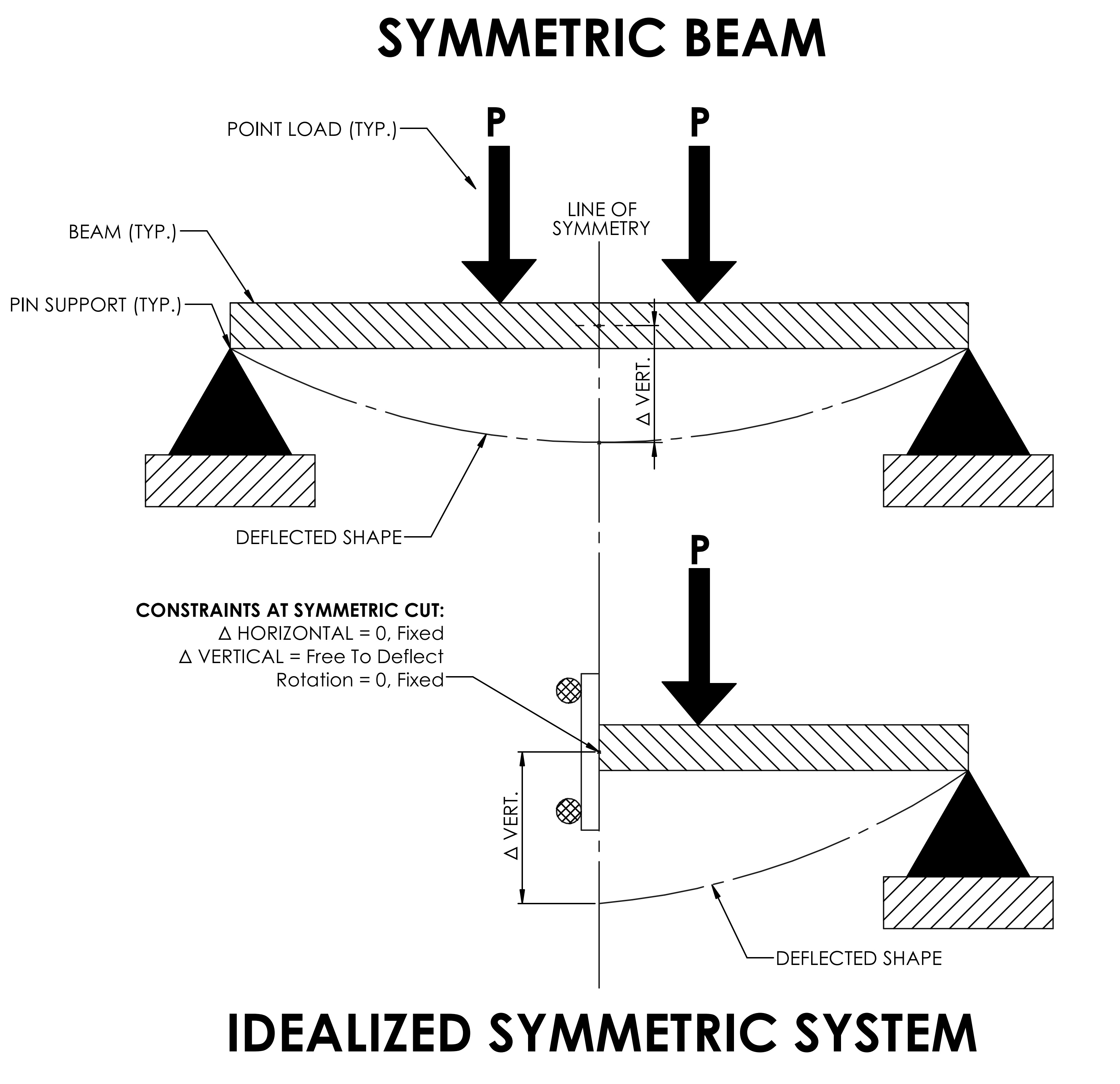
Symmetry can be used to model half the beam because the following constraints are known:
-
The rotation at the center of span is zero
-
The vertical displacement on both sides of the cut are identical
-
The lateral displacement on both sides of the cut is zero
Constraints
To take advantage of symmetry, the following must also be symmetric:
-
Loads
-
Support reactions
-
Material parameters
Case Study: FEA Analysis of HDPE Tank
Background

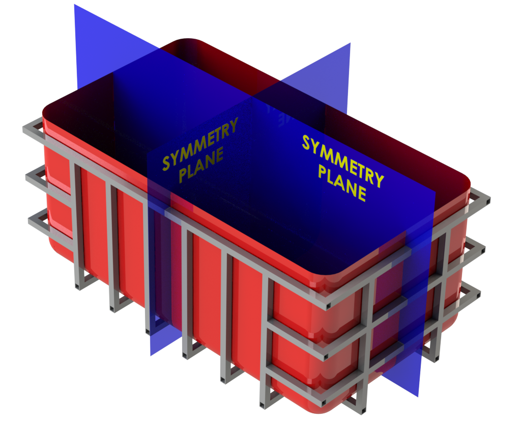
Consider a plastic HDPE tank supported by a structural steel frame. The HDPE tank is far more flexible than the steel supporting it. An analysis is required to verify the structural adequacy of the tank when filled with water.
Step 1: Determine Level of Symmetry
The structure (tank and frame) is doubly symmetric. The hydrostatic loading is also doubly symmetric due to the tank configuration. A symmetric analysis can be used for this structural evaluation.
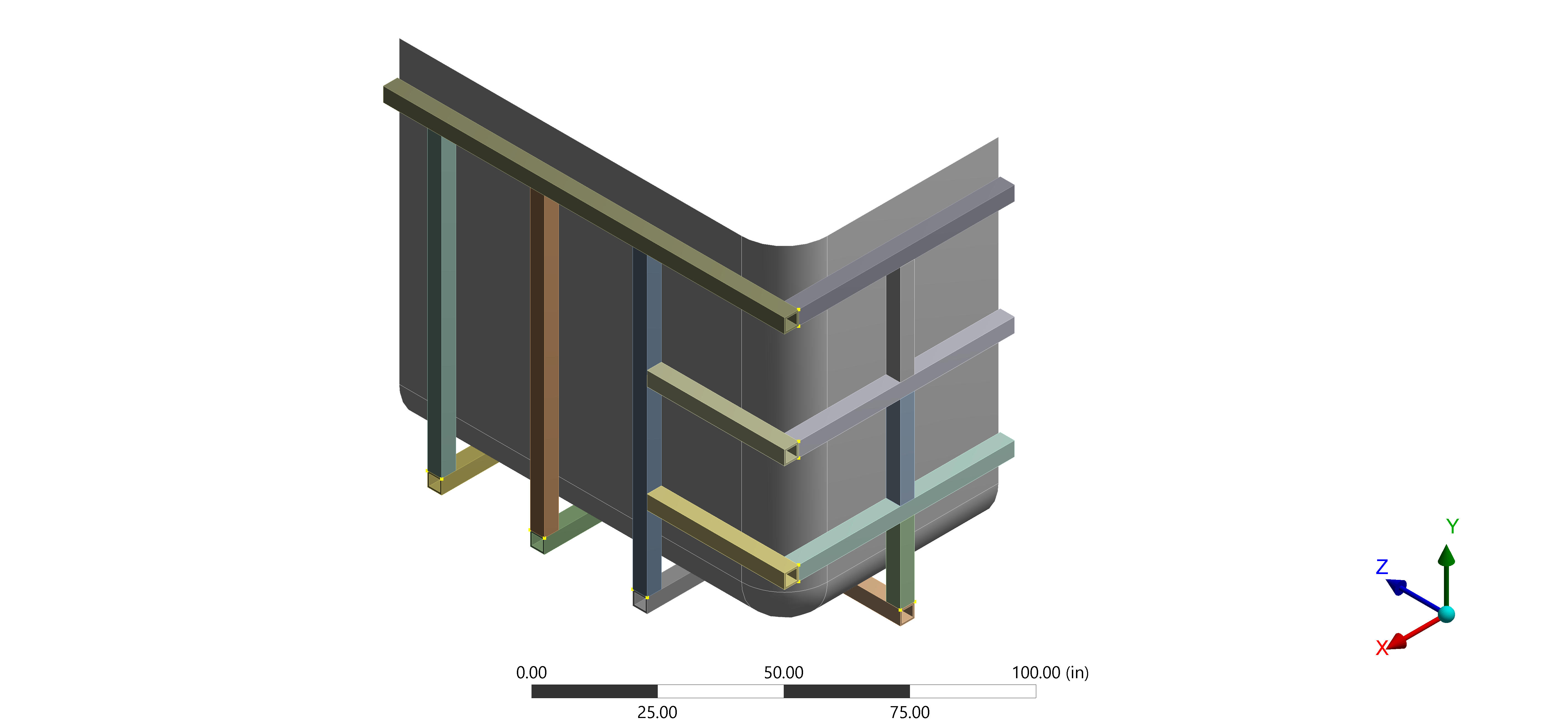
Step 2: Develop Geometry
Since the tank is doubly-symmetric, only a quarter of the tank needs to be modeled in the finite element analysis. A quarter of the geometry is extracted from Solidworks to LS-DYNA.
Step 3: Material Properties
The tank consists of a structural steel frame and HDPE tank. No plastic deformation is permitted during repeated tank filling. Tank materials are modeled as linear-elastic.
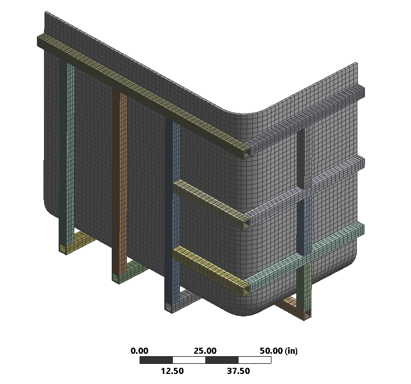
Step 4: Mesh
The tank and frame are meshed using solid elements. The mesh is refined in regions near the boundary cuts. The mesh is comprised of over 12,500 elements and 20,000 nodes.
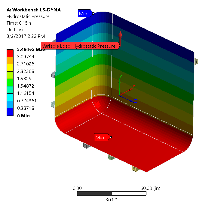
Step 5: Apply Loads
To mimic the tank contents, a hydrostatic load is applied to the HDPE tank. The hydrostatic load is an equivalent pressure loading that increases with tank depth.
Step 6: Apply Symmetric Boundary Conditions
The correct boundary conditions must be applied for symmetric analysis. With the symmetric hydrostatic loading the following boundary conditions are required:
-
Fixed Displacement: Displacement is fixed in directions perpendicular to the plane of cut. This constraint balances the forces in the system. This condition keeps the structure in static equilibrium.
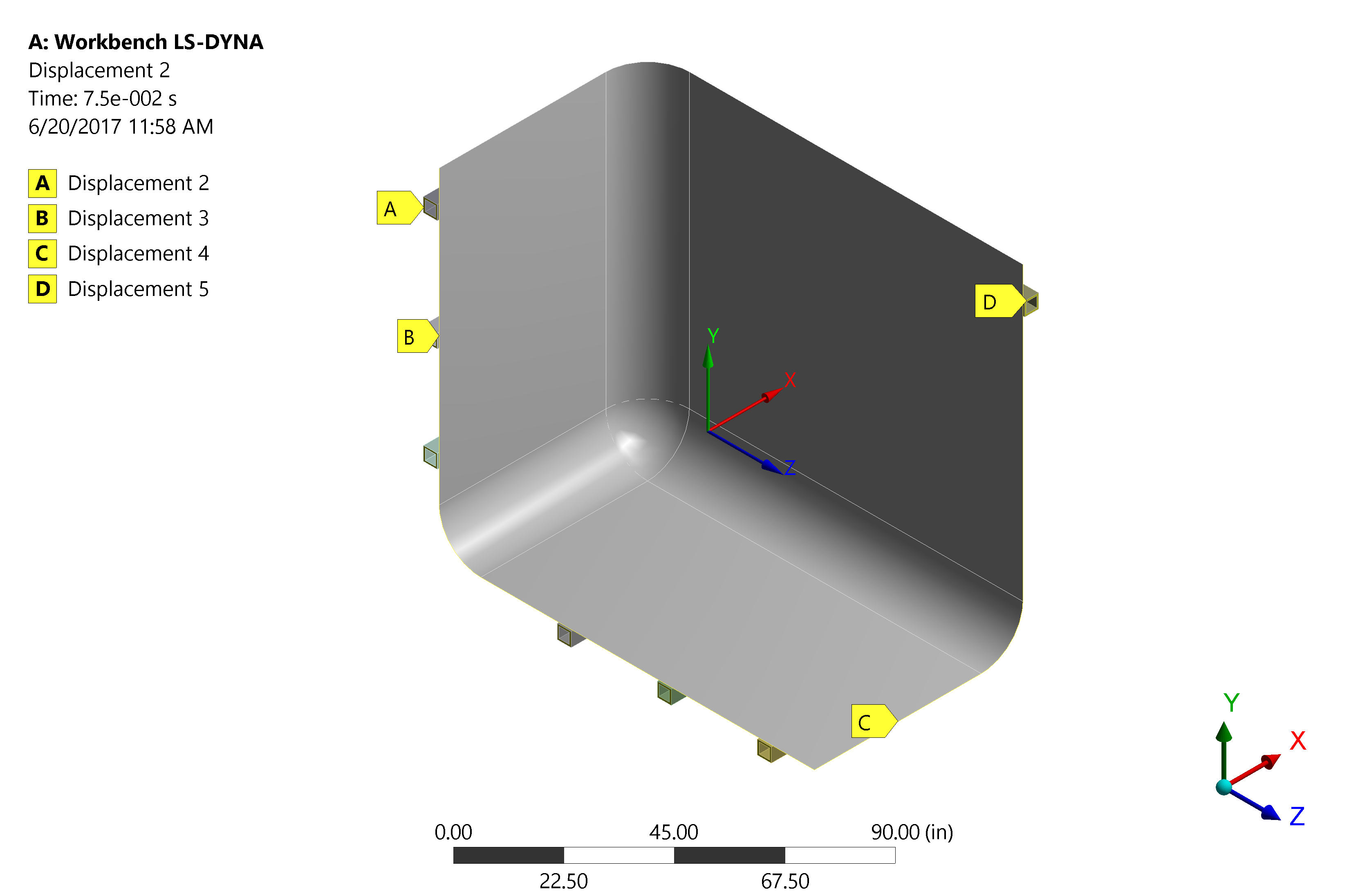
HDPE Tank Lateral Translation Boundary Conditions -
Fixed Rotation: Rotation at the cut is fixed at zero. This is because the structural system and loading is symmetric. In any symmetric system (structure and loads) the rotation at the center of the span will always be zero.
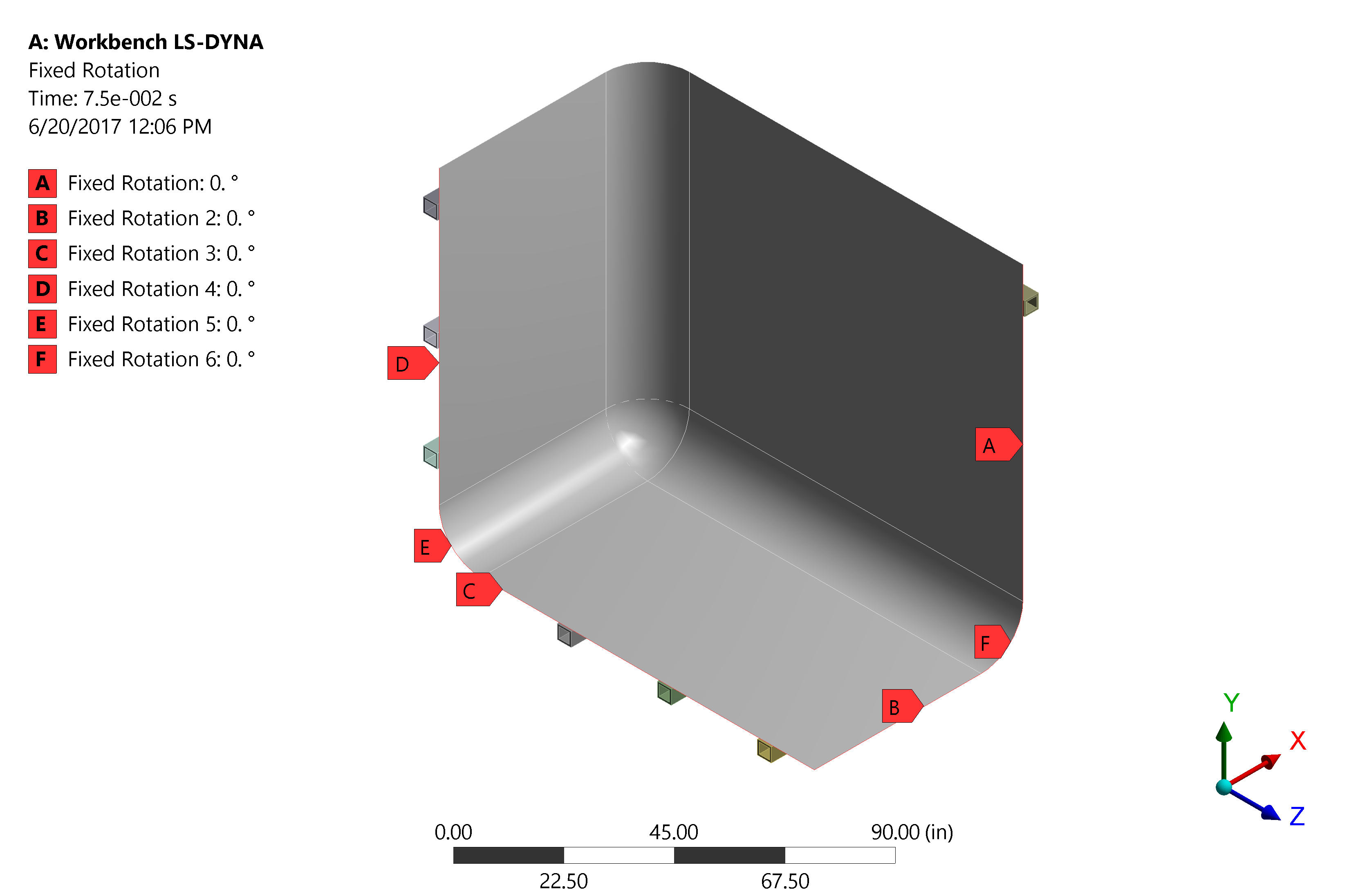
HDPE Tank Lateral Rotation Boundary Conditions
Step 7: Apply Remaining Boundary Conditions
To mimic the underlying ground, an additional vertical support reaction is applied. This application of this support is not symmetry dependent; however, we recognize that results represent load resulting from the quarter model only. The total load on the ground equals four times this result.
Step 8: Set-up & Solve
No additional solver controls are used for symmetric analysis.
Step 9: Model Validation
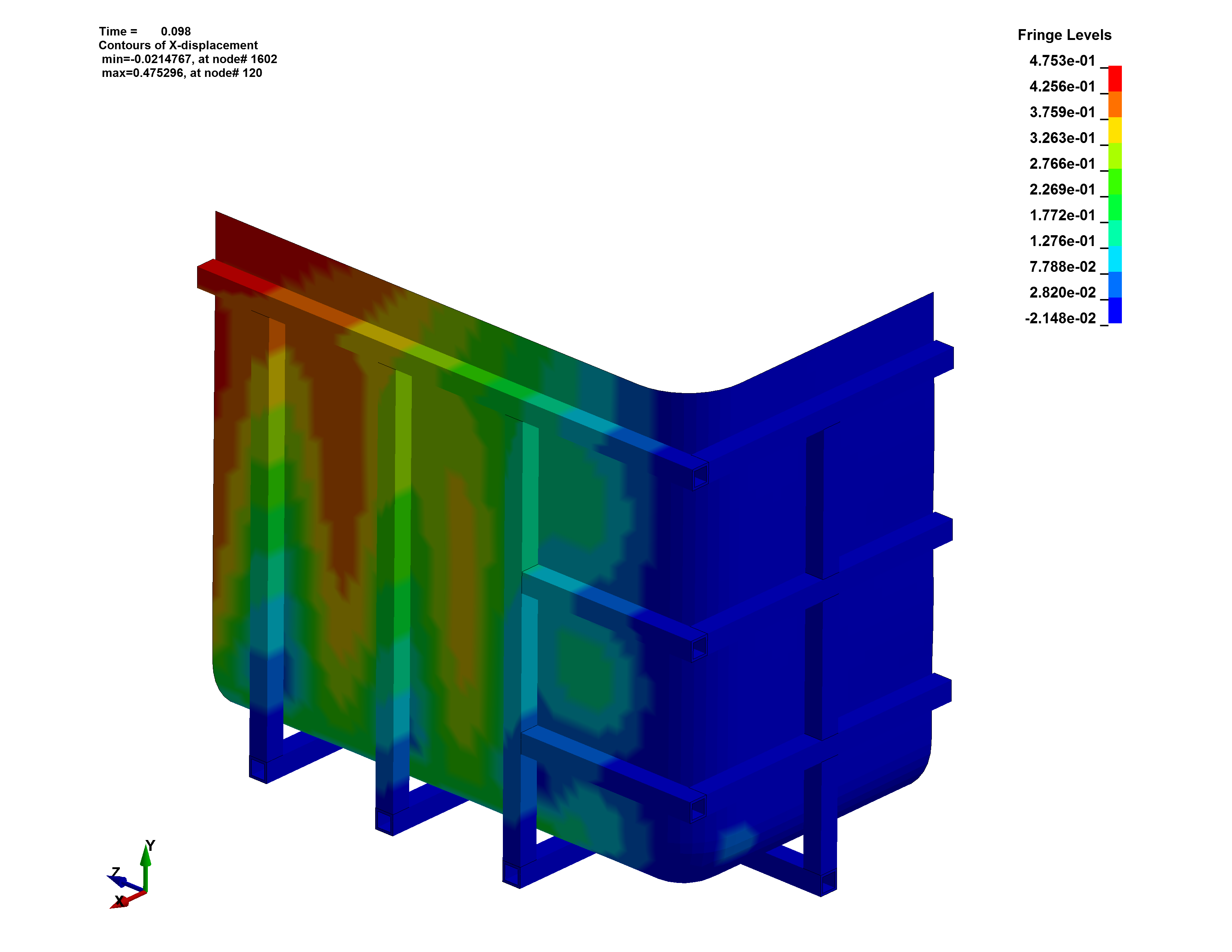
Tank displacement in each direction is shown below:
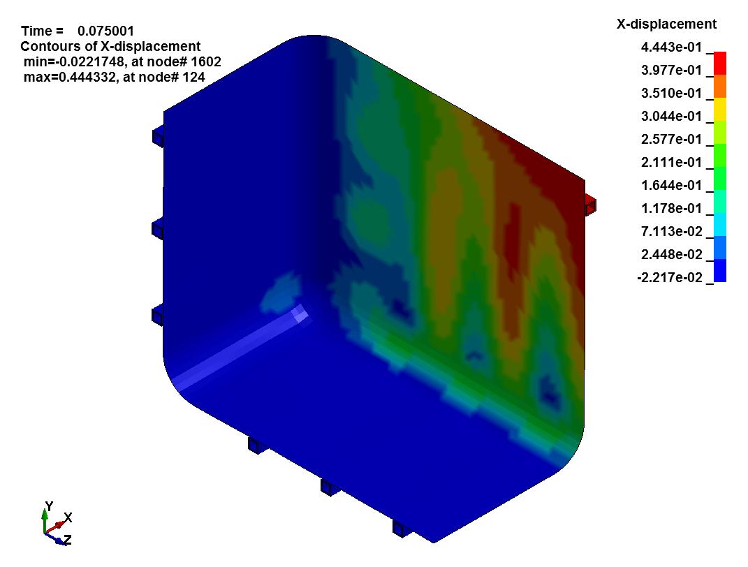
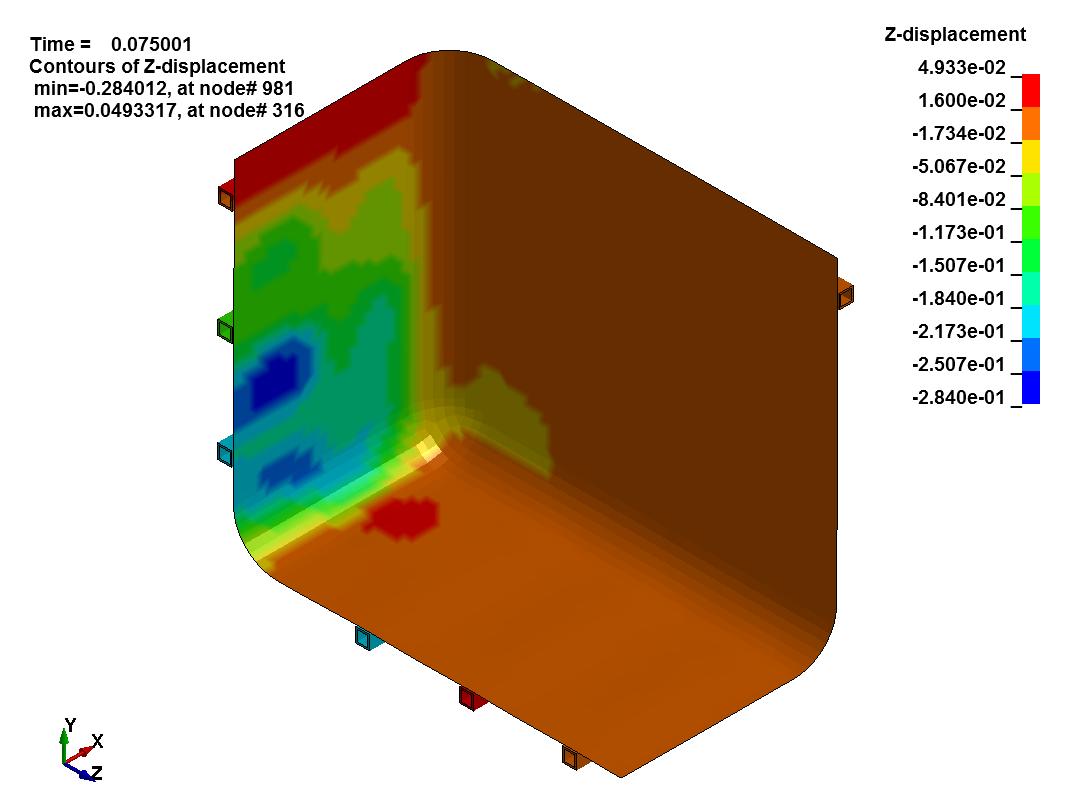
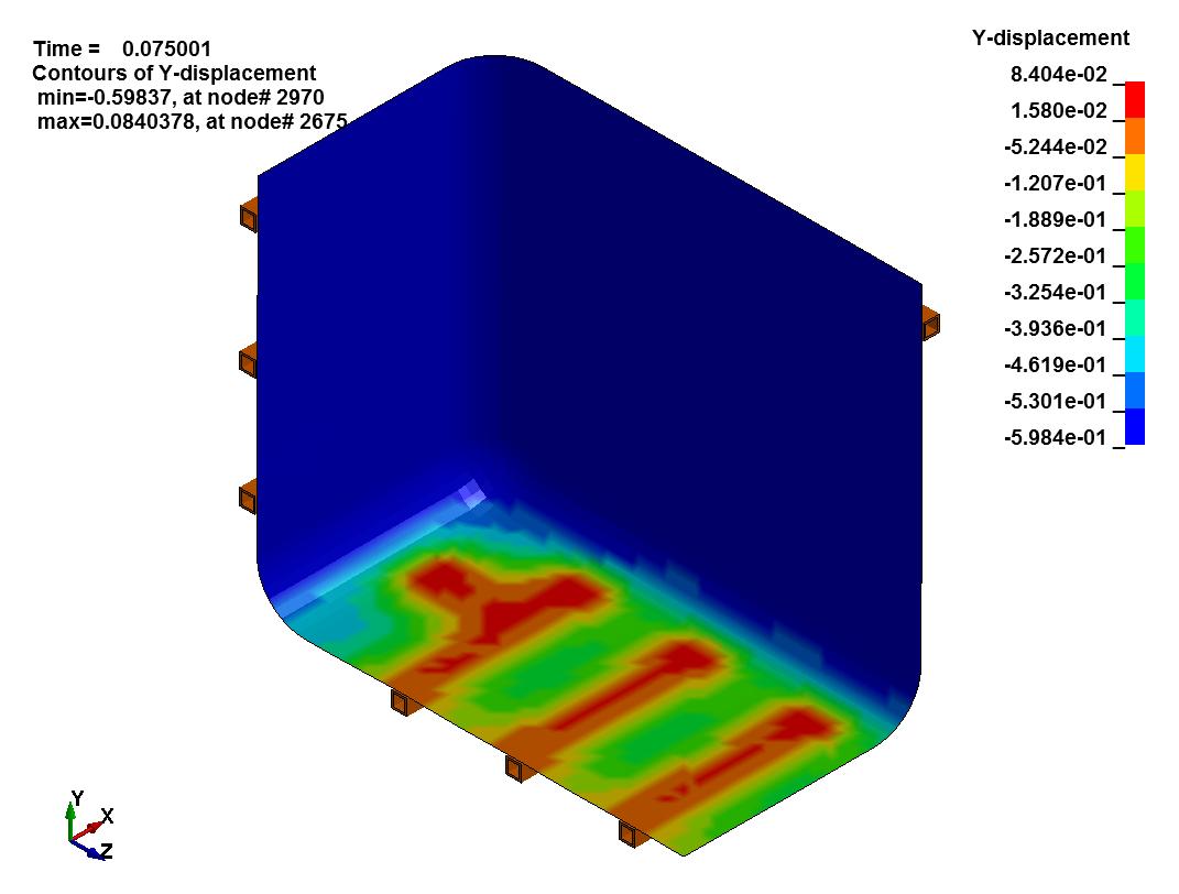
It’s crucial to understand if the results of the Finite Element Analysis are valid. In our tank example some simple checks confirm the accuracy of the symmetric analysis. They include:
-
Translation Parallel To Cut Plane: We see the structural frame and HDPE tank displacing laterally at our cuts. This makes sense, since we expect the tank walls to bow outward under hydrostatic load.
-
Translation Perpendicular To Cut Plane: There is no longitudinal displacement of the structural frame and HDPE tank at our cuts. This agrees with the laws of static equilibrium and the tank should remain at rest.
-
Rotation at Cut Surfaces: The faces of the structural frame and tank at our cuts do not rotate normal to the plane of symmetry. This makes sense, since we expect the cut to be in the center of a symmetric span where rotation is zero.
Step 10: Understanding Results:
It is important to understand symmetric FEA outputs. Some parameters may be actual values, while others may be a percentage. Stresses and deflections at the cuts are true values, but in our case, the vertical support reaction is only a quarter of the actual weight of the tank and its contents. This is because we only modeled one-quarter of the tank mass and equivalent hydrostatic force.
Step 11: Limitations of Analysis
It is important to understand the limitations of our FEA symmetric model. Two significant limitations of the FEA model are:
- Non-Symmetric Loading: The model cannot be used to evaluate singular non-symmetric loading.
- Dynamic Analysis: The model in its current form cannot be used for dynamic analysis. This is due to the fact that the model does not contain the mass of the water and lateral loading will result in an anti-symmetric response.
Symmetry in FEA: Essential Theory and Boundary Conditions
Taking advantage of symmetry allows the FEA analyst to reduce the size and scope of an analysis. In our doubly symmetric analysis of the HDPE tank, we were able to reduce model size by a factor of 4 while achieving accurate results.