Background
Nozzle Check valves are a great design, when used in the right application. As with anything else, if you use a great piece of equipment in the wrong application, you’re setting yourself up for failure.
A Primer on Nozzle Check Valves
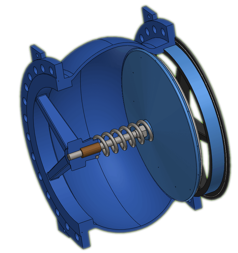
A check valve is very simple; it prevents flow in a piping system from going the wrong way. There are a number of difference ways to do this like a swing check valve, piston check, ball check, and the elegant nozzle check valve.
One of the problems with check valves is called water-hammer. Basically, when the check valve closes, it sends a pressure pulse down the pipe. If the valve closes faster, the pressure of the pulse is higher. Nozzle check valves have done a great job solving this problem. They’re designed to have a very short stroke length, so the disk doesn’t close as fast, and the pressure pulse is reduced. We’ve seen several applications where water-hammer was effectively eliminated by using Nozzle Check Valves.
Great Valve, Wrong Application
For years, a utility was struggling with leakage through a check valve (piston type). Engineers at the utility decided that replacing the valve with a nozzle check valve may help cut down on the problems, so they installed one. The valve was in service for about 1-2 fuel cycles (1.5-3 years) when it was discovered that the valve leakage was back and worse than ever before.
So What Happened?
XCEED Engineers worked with others at the site to find the cause of the problem. First, the valve was removed and replaced. We used forensic controls with the old valve, quarantining the part until it was brought to the metallurgy lab.
When we disassembled the valve, we found that the stem, originally a cylinder shape, was worn to a pencil tip. We did a surface exam, and found fretting on the surface. Basically, the stem wore so much that the disk didn’t seat anymore which allowed for the backflow.
So How did the Fretting happen?
Fretting is basically wearing of a surface by rubbing against another surface. Based on the location of the fretting wear, we figured out the that valve wore in the mid-position, not fully opened or closed. The valve shouldn’t ever be in the position.
Why did the valve wear in mid-stroke?
We looked at the design of the valve, and we found that the valve was designed for the normal AFW flow rate of about 200 gpm. The vendor design documents said that the flow had to stay above a certain amount (about 150 gpm) to make sure that the valve would go fully open.
So, no problem right?
Wrong.
We reviewed flow rates for the system since the valve was installed. During outages, we found that operators throttle the flow – as low as 50 gpm! And to go further, they leave the flow at 50 gpm for extended periods of time, even days.
So Why did this happen?
When the valve is at mid-stroke, any anomalies in the flow regime or pressure pulses can cause the valve disk and stem to move in and out a small amount. This is basically what happened, and it happened at a high frequency for days at a time. This was the perfect formula for fretting wear.
There was one more thing
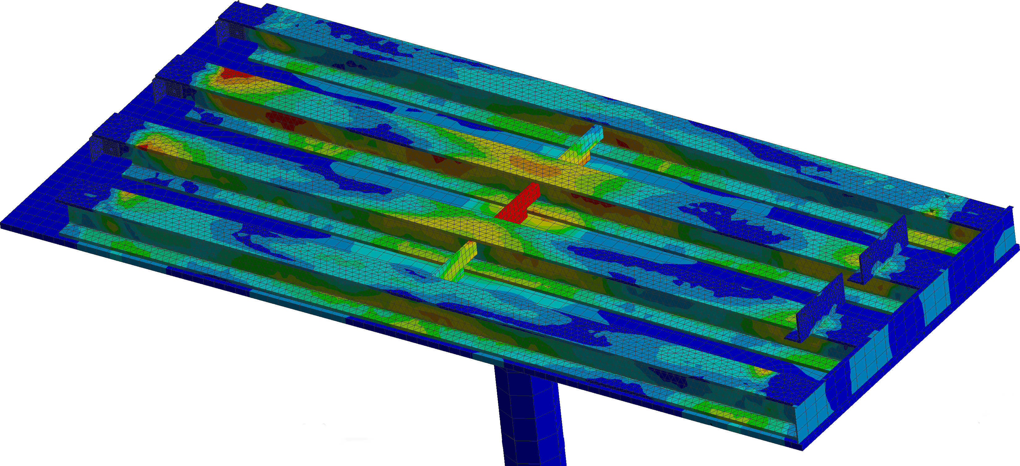
Some felt that the damage to the valve may have been caused by a flow vortex, making the disk spin at mid-span. The failure mode is similar, but the fretting wear was consistent with shorter strokes in the axial direction, not rotation of the disk. Still, some were not satisfied, so we resorted to one of our favorite tools – Computational Fluid Dynamics.
The piping system had two elbow upstream of the check valve that appeared to cause the fluid to have a vortex (rotational flow). We modeled the piping system, and reverse engineered the check valve so we could see if the rotational flow was in fact causing the disk to spin. We found that the flow was indeed rotational, but there wasn’t enough force imparted on the disk to get it to spin. The fluid merely flowed across the disk and through the valve. The friction between the stem and the bushing were enough to resist rotation.